 2024, Vol. 46
 Issue (5): 81-87


偏振是横向电磁波的一种重要性质,对于线偏振光、圆偏振光以及椭圆偏振光等常见光的检测是必需且具有实际意义的。传统光学器件因体积笨重等缺点无法满足现代光学设备对光学系统集成化的要求。一般利用方解石偏振器和波片来检测偏振态,而单一的器件很难同时检测多种偏振光的偏振态[1]。因此,需要设计一种可以同时检测多种偏振态且小型化的器件。
表面等离子体激元(surface plasmon polaritons,SPPs)是一种在金属与介电材料界面传播的电磁波[2-3]。SPPs具有短波长,对局域场有很强的束缚性以及对不同偏振光敏感的特性,引起了人们广泛的关注[4-6]。通过控制聚焦透镜能量振荡的振幅、相位、位置和数量,反衍射中许多难题得到了解决[7]。
在金属微纳米器件的设计中对光的振幅、相位及偏振进行调控,实现了全息成像[8]、光束分束器[9-10]、涡旋光生成器[11]、超透镜[12]等功能。Xu等[13]通过分离狭缝自由控制激发SPPs的幅值和相位,基于全息原理分离狭缝来记录目标像素的振幅和相位,从而得到任意所需的全息图像剖面。Jin等[14]基于传播相位与激发相位相等原理,实现了单柱悬链孔阵列对圆偏振光进行高效分束,实验消光比结果达到495。Chen等[15]通过分析悬链孔的电磁场模式以及基于惠更斯–菲涅尔原理实现了悬链孔阵列对线偏振光的分束。Yang等[16]提出一种L型和十字型纳米狭缝组成的圆形结构,实现了偏振控制的可切换涡旋光生成器。Qiu等[17]提出了一种微米级长的亚波长狭缝和两组空间排列的周期性亚波长矩形槽对组成的偏振分析仪,可以根据不同周期的干涉条纹来直接或定量的区分圆偏振光手性。但以上所有研究基于同一个结构,仅对线偏振光或者圆偏振光敏感。同时对多种偏振态敏感的器件目前并不多见。
本课题组曾于2022年和2023年设计出基于介电材料,可用于区分偏振态的器件[18-19]。为了更简单有效地区分多种偏振光的偏振态,基于悬链孔多种电场模式的特性,本文设计了一种悬链孔组成的器件,利用时域有限差分(finite difference time domain,FDTD)软件,在入射光源波长为632 nm时,计算了单元悬链孔结构的透射场模式和器件的中心透射场电场分布,并完成了中心电场分布的理论验证。
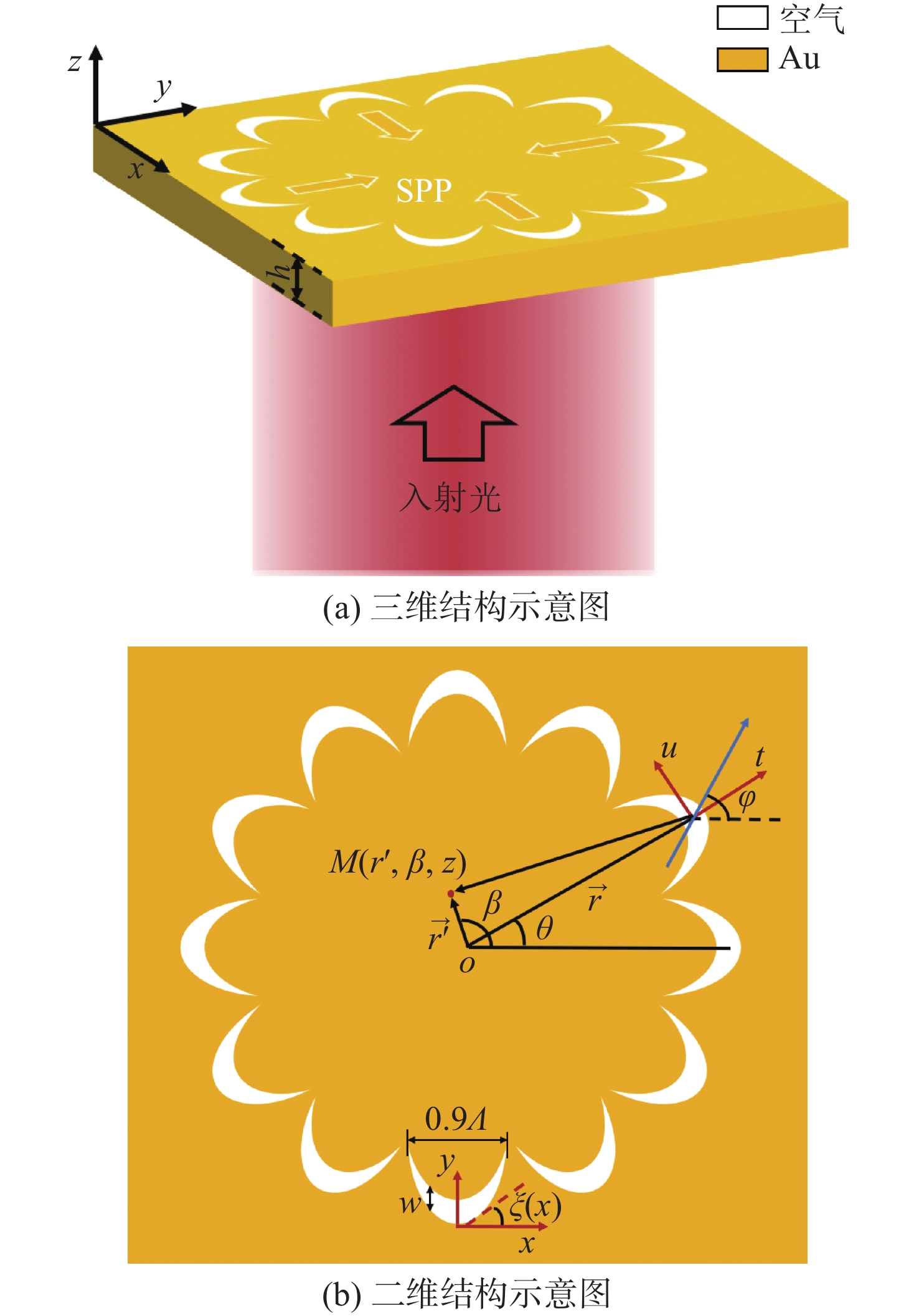
1 器件设计所设计的偏振分析仪是基于悬链线纳米孔单元结构组成的,如图1所示。器件由单层金(Au)组成,厚度h = 110 nm,半径r = 1 250 nm。金层刻蚀的悬链孔沿着圆形来排列,悬链孔的开口垂直于径向方向。选取Au作为器件的材料,是因为Au材料可以更好地激发表面等离子体激元,性质相对稳定且方便加工。
|
图 1 偏振分析仪结构图 Figure 1 Structure diagram of polarization |
悬链孔由非均匀各向异性材料中自旋–轨道相互作用产生的空间变化的缝组成[20]。假定ξ为狭缝与x坐标轴之间的夹角,ϕ为几何相位,悬链孔几何相位与纳米矩形狭缝相似,ϕ = 2σξ(σ = ±1,分别对应于左旋圆偏振光和右旋圆偏振光),如图1(b)所示。悬链孔的设计通常需要两步:首先根据所需的目标相位分布以及ϕ = 2σξ的关系,可以得到空间变化角度ξ(x, y);然后对正切值tan ξ(x, y)进行积分,对于沿着x轴方向的线性相位分布dy/dx = tan(πx/Λ)可以直接在x轴上积分得到式(1)[21]。本文悬链纳米孔是由两条悬链线构成,其中一条沿着y轴方向移动w = 130 nm,围成单元悬链孔结构,悬链线曲线可表示为“等相位梯度悬链线”,同Davies Gilbert提出的“等强度悬链线”[22]类似,表达式为
| $ y=-\left(\frac{\varLambda }{{\text{π}}}\right)\mathrm{ln}\left|\mathrm{cos}\left(\frac{{\text{π}}x}{\varLambda }\right)\right| $ | (1) |
式中,Λ是悬链孔在x方向的宽度,因为两条悬链线的交点在x = ± Λ/2时,y的坐标值为无穷大。根据实际加工情况需要对悬链线进行截断处理,本文设计的交点位置在y = ± 0.45Λ处,所以最终悬链孔的实际开口长度为0.9Λ = 540 nm。
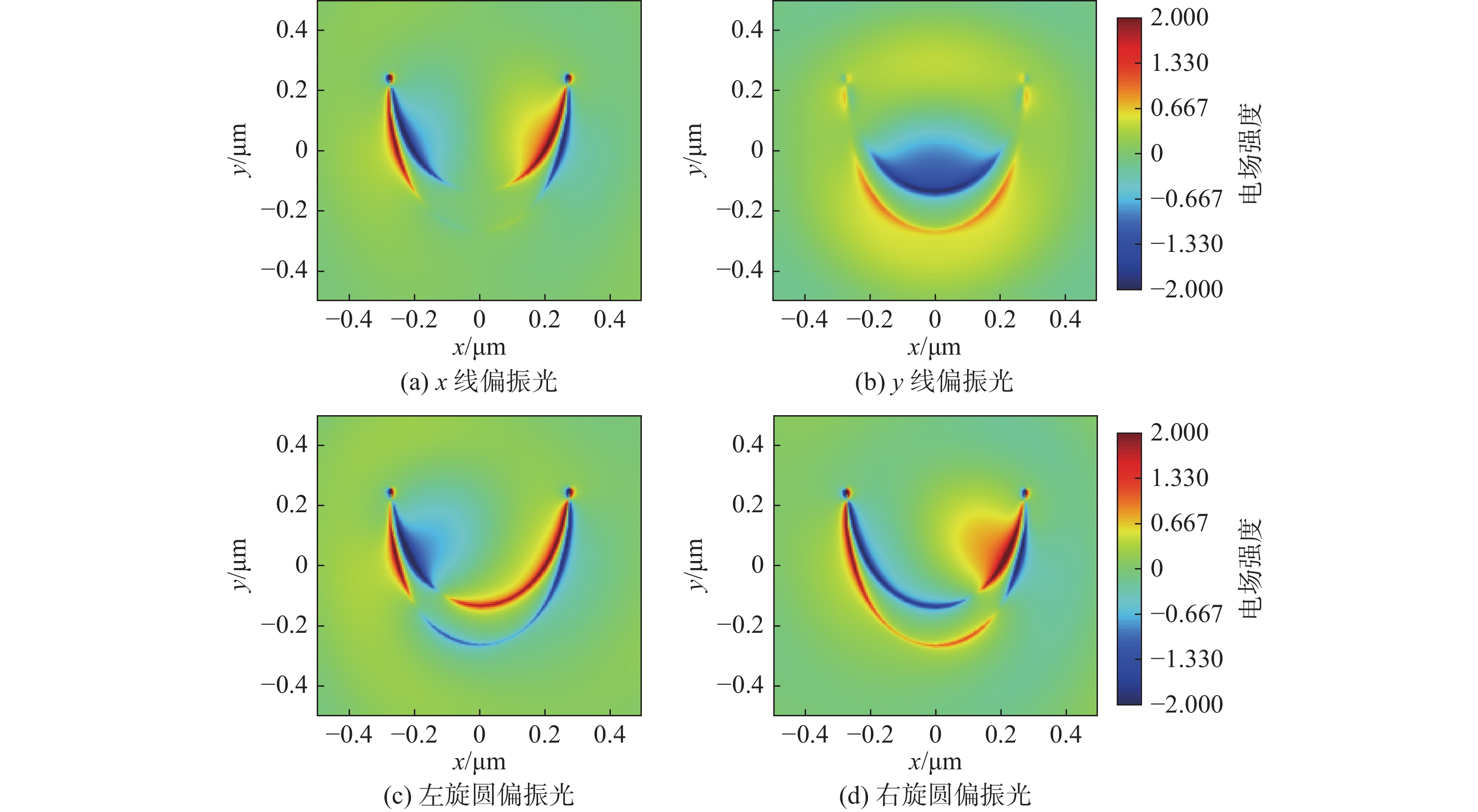
2 原理分析为了分析单元悬链孔的SPPs定向激发的原理,利用FDTD软件对单元悬链孔中的透射电场进行模拟分析。在笛卡尔坐标系中,对x线偏振光、y线偏振光、左旋圆偏振光和右旋圆偏振光入射下的单元悬链孔透射电场分布情况进行探究。在仿真模拟中,光源从结构下方沿着+ z方向垂直入射,边界条件采用完全匹配层(perfectly matched layer,PML),网格尺寸考虑到精细程度设置为 2 nm × 2 nm × 2 nm,选用总场散射场(total-field scattered-field,TFSF)作为入射到悬链孔的平面光源,Au材料的相对介电常数与波长的函数关系取自Palik数据[23]。得到的悬链孔多种透射电场模式如图2所示。
|
图 2 不同偏振光源入射下的单元悬链孔电场分布图 Figure 2 Electric field distribution of catenary under different polarization light sources |
本文计算了在实验室常用波长632 nm处不同偏振光入射时悬链孔的电场分布。x线偏振光入射时,悬链孔透射电场表现为电四极子模式,由于悬链孔径关于y方向上对称,金属空气表面激发的SPPs在± x方向上对称分布,如图2(a)所示。y线偏振光入射时,悬链孔透射场符合偶极子模式特性,悬链孔电荷主要分布在悬链孔内腰处,由于悬链孔内外腰处电场强度不同且内腰的电场强度大于外腰,导致SPPs的定向激发,如图2(b)所示。左旋圆偏振光入射时,基于圆偏振光的自旋–轨道相互作用[24-25],悬链孔的透射电场表现为顺时针的电四极子模式,电荷集中在内腰的左侧,如图2(c)所示。对于右旋圆偏振光,透射场与左旋圆偏振光相反,透射电场表现为逆时针的电四极子模式,电荷集中在内腰的右侧,如图2(d)所示。因此,丰富的透射电场模式有利于实现高效的定向激发SPPs。
为了探究器件中心光场的聚焦情况,从光的偏振态开始研究。在笛卡尔坐标系中,对于沿着z轴传播的电磁波,电场只有x和y分量,可表示为
| $ {E}_{x}={E}_{0x}\mathrm{cos}\left(\tau +{\delta }_{1}\right) $ |
| $ {E}_{y}={E}_{0y}\mathrm{cos}\left(\tau +{\delta }_{2}\right) $ |
故任意偏振光可表示为
| $ \frac{{E}_{y}}{{E}_{x}}=\frac{{E}_{0y}}{{E}_{0x}}{\mathrm{e}}^{\mathrm{i}\delta } $ | (2) |
式中:
因为悬链孔的大小小于SPPs波长,根据惠更斯–菲涅尔原理[26],可以将悬链孔看成点光源。本文采用琼斯矢量的方法来表示偏振光,左旋圆偏振光为
| $ \begin{split} {\overrightarrow{\boldsymbol{E}}}_{\mathrm{M}}&=C{\overrightarrow{\boldsymbol{E}}}_{\mathrm{i}\mathrm{n}}\overrightarrow{\boldsymbol{t}}{{\mathrm{e}}^{-kz}\mathrm{e}}^{\mathrm{i}{\overrightarrow{\boldsymbol{k}}}_{\mathrm{s}\mathrm{p}\mathrm{p}}\left(\overrightarrow{{\boldsymbol{r}}{\boldsymbol{{'}}}}-\overrightarrow{\boldsymbol{r}}\right)}\overrightarrow{\boldsymbol{a}} \\& =C{\overrightarrow{\boldsymbol{E}}}_{\mathrm{i}\mathrm{n}}\overrightarrow{\boldsymbol{t}}{{\mathrm{e}}^{-kz}\mathrm{e}}^{\mathrm{i}({k}_{\mathrm{s}\mathrm{p}\mathrm{p}}r-{k}_{\mathrm{s}\mathrm{p}\mathrm{p}}{r}{{'}}\mathrm{cos}\left(\beta -\theta \right))}\overrightarrow{\boldsymbol{a}} \end{split}$ | (3) |
式中:
当悬链孔单元足够多时,器件中心电场的大小可近似为
| $ E={\int }_{0}^{2{\text{π}}}{{\boldsymbol{E}}}_{{\rm{M}}}{\rm{d}}\theta $ | (4) |
器件中心附近的总场是悬链孔辐射的叠加,附近各孔的辐射场主要含有z分量,所以总辐射场可简化为悬链孔的辐射之和。在线偏振光照射时,器件中心的透射场
| $ \begin{split} {E}_{\mathrm{L}}&={\int }_{0}^{2{\text{π}}}C{\overrightarrow{\boldsymbol{E}}}_{\mathrm{l}}\overrightarrow{\boldsymbol{t}}{{\mathrm{e}}^{-kz}\mathrm{e}}^{\mathrm{i}{\overrightarrow{\boldsymbol{k}}}_{\mathrm{s}\mathrm{p}\mathrm{p}}\left(\overrightarrow{{\boldsymbol{r}}{\boldsymbol{{'}}}}-\overrightarrow{\boldsymbol{r}}\right)}{\rm{d}}\theta\\ &=C{\mathrm{e}}^{-kz}{\mathrm{e}}^{{\mathrm{i}k}_{\mathrm{s}\mathrm{p}\mathrm{p}}{r}_{0}}{\int }_{0}^{2{\text{π}}}-\mathrm{cos}\left(\varphi -\theta \right){\mathrm{e}}^{-\mathrm{i}{k}_{\mathrm{s}\mathrm{p}\mathrm{p}}{r}{{'}}\mathrm{cos}\left(\beta -\theta \right)}{\rm{d}}\theta \\ & \propto {\mathrm{e}}^{\mathrm{i}\left(\beta -\varphi \right)}{\mathrm{J}}_{1}\left({k}_{\mathrm{s}\mathrm{p}\mathrm{p}}{r}{{'}}\right) \end{split} $ | (5) |
式中:
当圆偏振光入射时,因为偏振角
| $ \begin{split} {E}_{\mathrm{L}\mathrm{C}\mathrm{P}} = & {\int }_{0}^{2{\text{π}}}C{\overrightarrow{\boldsymbol{E}}}_{\mathrm{L}}\overrightarrow{\boldsymbol{t}}{{\mathrm{e}}^{ -kz}{\mathrm{e}}^{\varphi \left(\theta \right)}\mathrm{e}}^{\mathrm{i}{\overrightarrow{\boldsymbol{k}}}_{\mathrm{s}\mathrm{p}\mathrm{p}}\left(\overrightarrow{{\boldsymbol{r}}{\boldsymbol{{'}}}} - \overrightarrow{\boldsymbol{r}}\right)}{\rm{d}}\theta \propto \\ & {\mathrm{e}}^{ -\mathrm{i}\beta }{\mathrm{J}}_{1}\left({k}_{\mathrm{s}\mathrm{p}\mathrm{p}}{r}{{'}}\right) \end{split}$ | (6) |
| $\begin{split} {E}_{\mathrm{R}\mathrm{C}\mathrm{P}} = & {\int }_{0}^{2{\text{π}}}C{\overrightarrow{\boldsymbol{E}}}_{\mathrm{R}}\overrightarrow{\boldsymbol{t}}{{\mathrm{e}}^{-kz}{\mathrm{e}}^{\varphi \left(\theta \right)}\mathrm{e}}^{\mathrm{i}{\overrightarrow{\boldsymbol{k}}}_{\mathrm{s}\mathrm{p}\mathrm{p}}\left(\overrightarrow{{\boldsymbol{r}}{\boldsymbol{{'}}}}-\overrightarrow{\boldsymbol{r}}\right)}{\rm{d}}\theta \propto \\ & {\mathrm{e}}^{\mathrm{i}\beta }{\mathrm{J}}_{1}\left({k}_{\mathrm{s}\mathrm{p}\mathrm{p}}{r}{{'}}\right) \end{split} $ | (7) |
式中,
因为径向偏振光始终有偏振角
| $ {E}_{\mathrm{R}}={\int }_{0}^{2{\text{π}}}C{\overrightarrow{\boldsymbol{E}}}_{\mathrm{r}}\overrightarrow{\boldsymbol{t}}{{\mathrm{e}}^{-kz}\mathrm{e}}^{\mathrm{i}{\overrightarrow{\boldsymbol{k}}}_{\mathrm{s}\mathrm{p}\mathrm{p}}\left(\overrightarrow{{\boldsymbol{r}}{\boldsymbol{{'}}}}-\overrightarrow{\boldsymbol{r}}\right)}{\rm{d}}\theta \propto {\mathrm{J}}_{0}\left({k}_{\mathrm{s}\mathrm{p}\mathrm{p}}{r}{{'}}\right) $ | (8) |
式中:
当角向偏振光入射时,器件中心的透射电场
| $ {E}_{\mathrm{A}}={\int }_{0}^{2{\text{π}}}C{\overrightarrow{\boldsymbol{E}}}_{a}\overrightarrow{\boldsymbol{t}}{{\mathrm{e}}^{-kz}\mathrm{e}}^{\mathrm{i}{\overrightarrow{\boldsymbol{k}}}_{\mathrm{s}\mathrm{p}\mathrm{p}}\left(\overrightarrow{{\boldsymbol{r}}{\boldsymbol{{'}}}}-\overrightarrow{\boldsymbol{r}}\right)}{\rm{d}}\theta =0 $ | (9) |
式中
为了验证上述理论和器件的可靠性,利用时域有限差分FDTD软件对偏振角为0°,30°,60°以及90°的线偏振光照射下器件的透射场|Ez|进行了仿真模拟,如图3所示。在x-y平面上透射电场|Ez|的中心成多层瓣状,器件中心的瓣状分别对应呈现0°,30°,60°以及90°方向的电场分布,可以用式(5)来解释,与
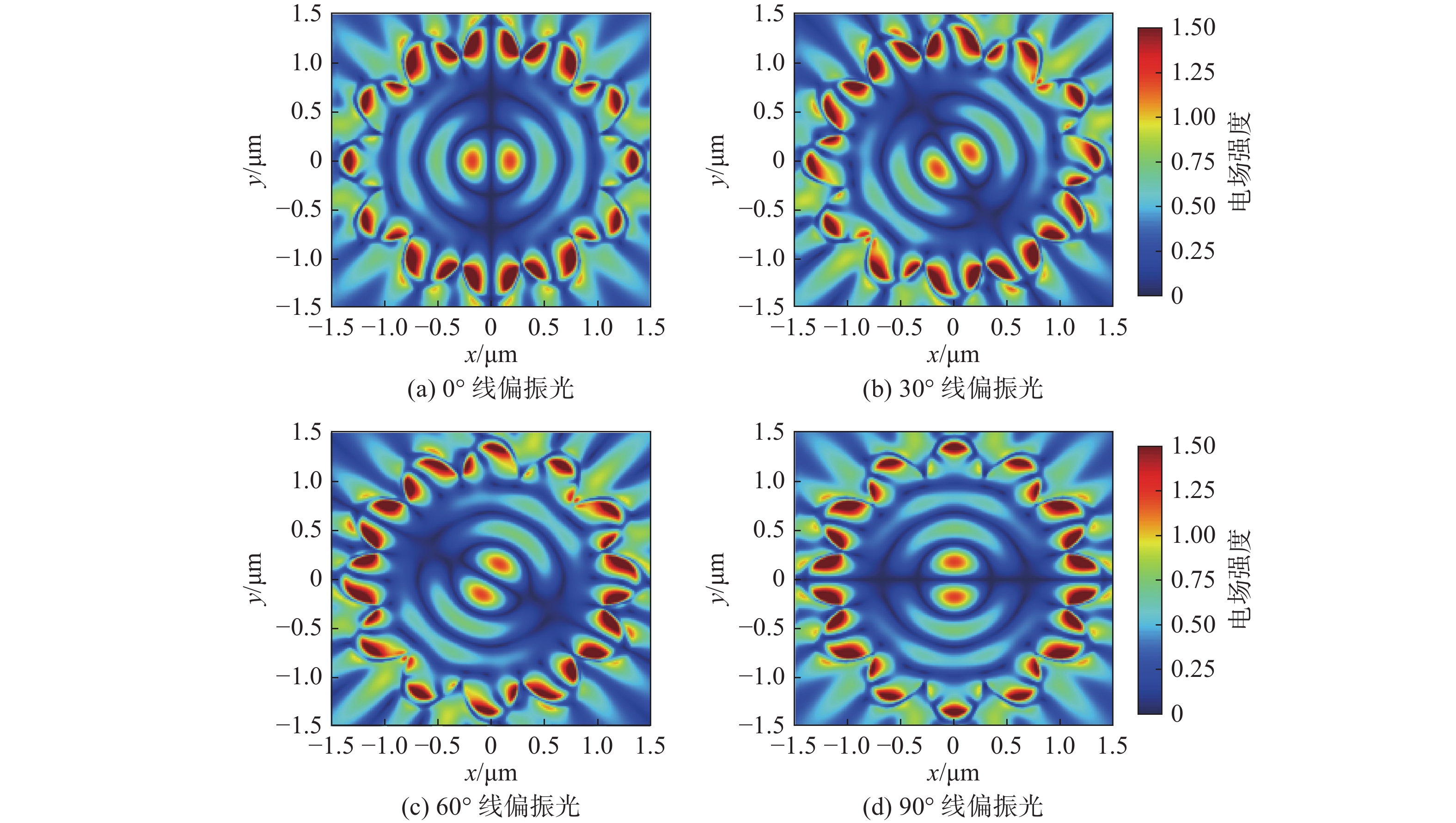
|
图 3 线偏振光入射时透射场|Ez|分布图 Figure 3 Transmission field |Ez| distribution of linearly polarized light incidence |
左旋圆偏振光和右旋圆偏振光入射时都将在器件中心形成“甜甜圈”状透射电场,符合式(6)和式(7)。当左旋圆偏振光入射时,可以清楚地发现悬链孔出现“蝌蚪状”且顺时针旋转的电场分布,并且在图4右下角插入的相位图中显示生成了拓扑数为
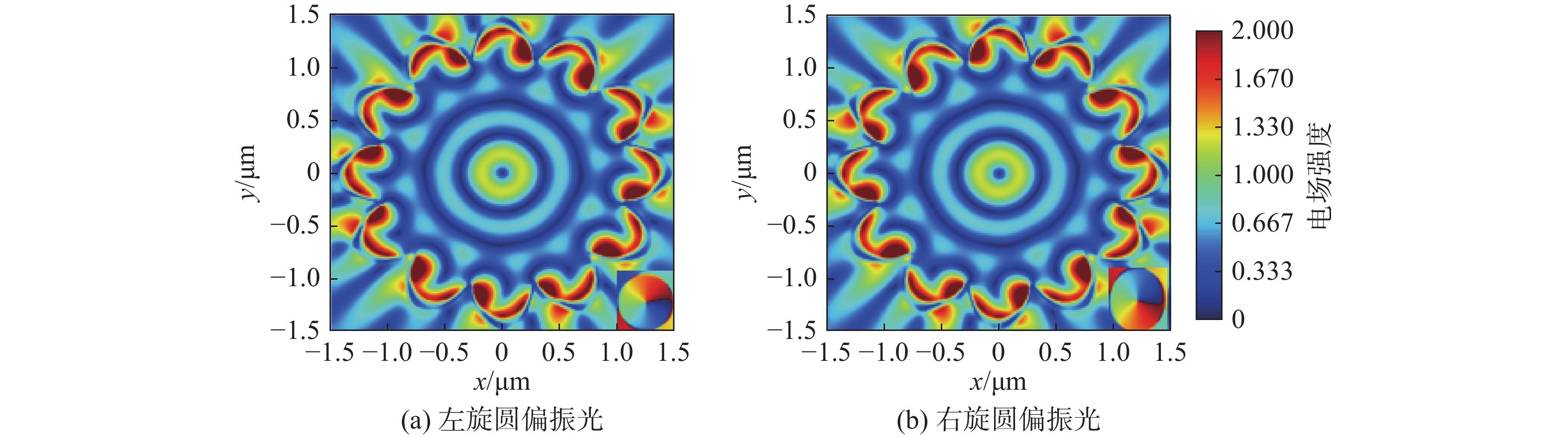
|
图 4 圆偏振光入射时透射场|Ez|分布图 Figure 4 Transmission field |Ez| distribution of circularly polarized light incident |
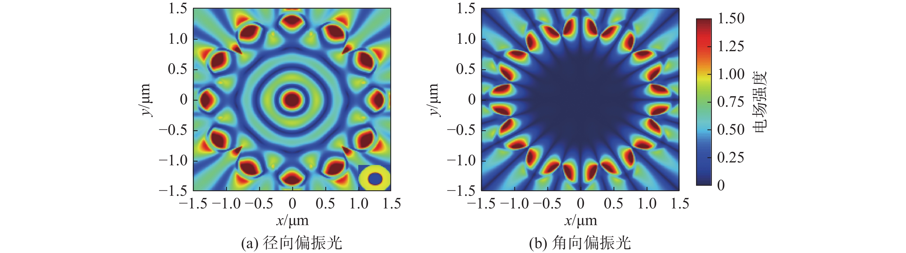
矢量光(径向偏振光和角向偏振光)照射时,器件中心透射场也呈现出不同的电场分布。当径向偏振光照射时,器件中心透射场呈现聚焦亮斑,从图5(a)右下角插入的相位图中可以得到其相位满足零阶贝塞尔函数,符合式(8);对于角向偏振光入射时,器件中心无电场形成,如图5所示。基于悬链孔电场模式,当入射光沿着悬链孔开口方向时,悬链孔激发的SPPs沿着悬链孔开口方向激发传播,所以器件中心电场为0。
|
图 5 矢量偏振光入射时透射场|Ez|分布图 Figure 5 Transmission field |Ez| distribution of vector polarized light incidence |
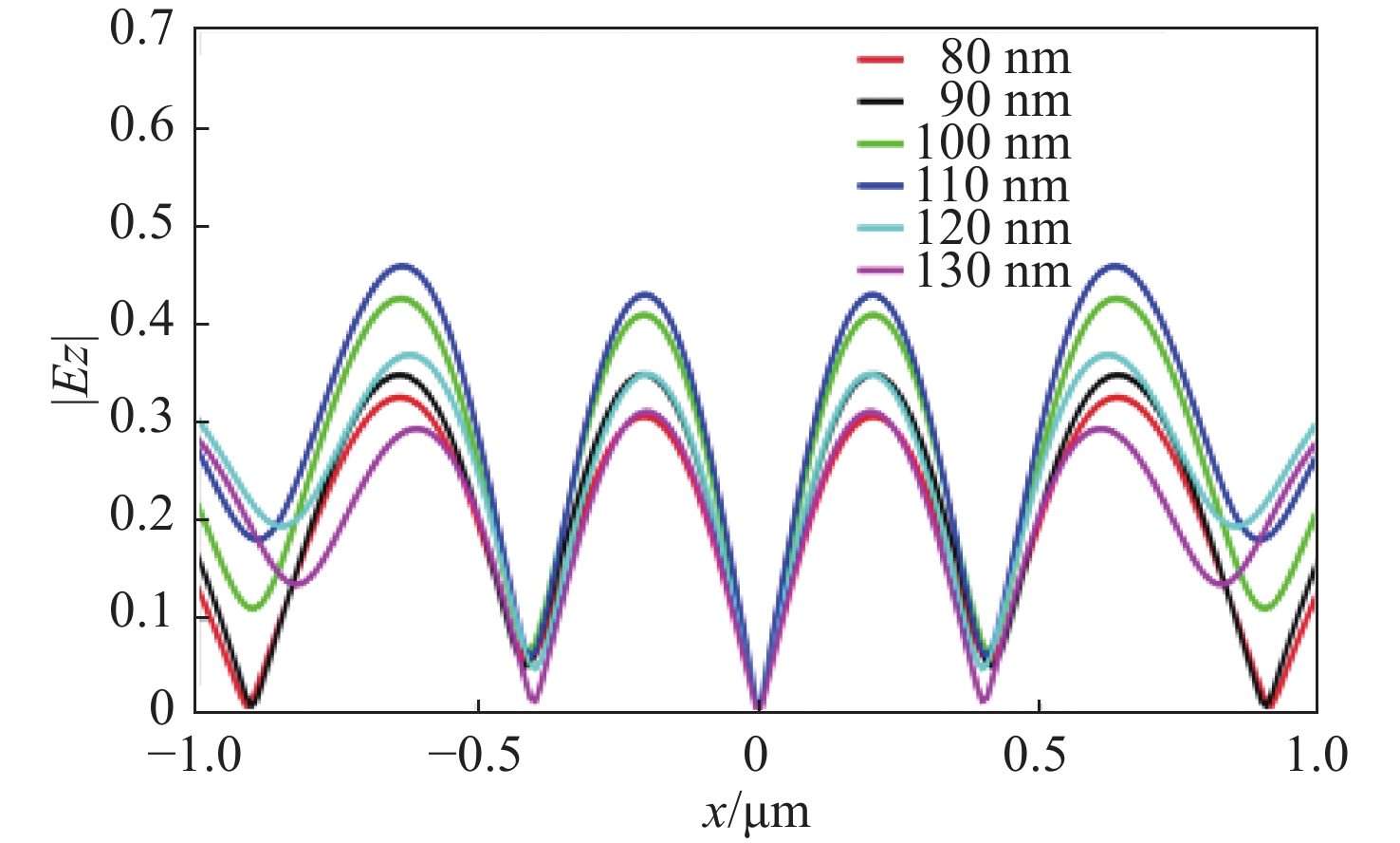
此外,本文通过改变金层的厚度分析了器件透射中心电场强度,用于优化设计出相对更好的结构尺寸。为了简化工作量,仅对0°线偏振光入射时器件中心透射电场进行了讨论分析,如图6所示。
|
图 6 不同金层厚度器件透射场图 Figure 6 Transmission field of devices with different gold thicknesses |
结果表明,对于0°线偏振光入射时,器件中心瓣状电场强度在金层厚度为110 nm时最高;金层厚度越厚,相长干涉点和相消干涉点越往器件中心靠近。
4 结 论本文设计并数值验证了一种基于表面等离子体激元的偏振分析器件,计算出不同偏振光入射时单元悬链孔的电场模式,并且推导出不同偏振光下器件透射场表达式。不同偏振光入射时,悬链孔的多种电场模式和器件中心电场理论计算结果的差异化预示着器件性能的优异性,器件透射场的数值模拟结果给予了有力的验证,相比于现有的表面等离子体激元偏振分析器件,本文设计无需测量斯托克斯参数且可检测多种偏振态。因此,本文的工作对偏振分析器的设计有一定的指导意义,悬链孔的电场模式和理论推导结果对SPPs的定向传播控制也有一定帮助。
| [1] | ZHANG Q, LI P Y, LI Y Y, et al. A universal plasmonic polarization state analyzer[J]. Plasmonics, 2018, 13(4): 1129–1134. |
| [2] | BARNES W L, DEREUX A, EBBESEN T W. Surface Plasmon subwavelength optics[J]. Nature, 2003, 424(6950): 824–830. |
| [3] | OZBAY E. Plasmonics: merging photonics and electronics at nanoscale dimensions[J]. Science, 2006, 311(5758): 189–193. |
| [4] | ZHANG J Y, DAI J W, YANG J, et al. Invertible plasmonic spin-Hall effect at nanoscale based on U-shaped optical slot nanoantenna[J]. Nanotechnology, 2019, 30(34): 345201. |
| [5] | VERCRUYSSE D, NEUTENS P, LAGAE L, et al. Single asymmetric plasmonic antenna as a directional coupler to a dielectric waveguide[J]. ACS Photonics, 2017, 4(6): 1398–1402. |
| [6] | GUAN X W, WU H, SHI Y C, et al. Extremely small polarization beam splitter based on a multimode interference coupler with a silicon hybrid plasmonic waveguide[J]. Optics Letters, 2014, 39(2): 259–262. |
| [7] | WENG X Y, SONG Q, LI X M, et al. Free-space creation of ultralong anti-diffracting beam with multiple energy oscillations adjusted using optical pen[J]. Nature Communications, 2018, 9(1): 5035. |
| [8] | YANG Y, KIM H, BADLOE T, et al. Gap-Plasmon-driven spin angular momentum selection of chiral metasurfaces for intensity-tunable metaholography working at visible frequencies[J]. Nanophotonics, 2022, 11(17): 4123–4133. |
| [9] | CHEN P P, CHEN C, XI J X, et al. Multi-directional plasmonic splitter and polarization analyzer based on the catenary metasurface[J]. Plasmonics, 2022, 17(1): 43–49. |
| [10] | GUO Y H, PU M B, LI X, et al. Ultra-broadband spin-controlled directional router based on single optical catenary integrated on silicon waveguide[J]. Applied Physics Express, 2018, 11(9): 092202. |
| [11] | GAO L, RUI G H, DING C C, et al. Generating plasmonic vortex field with spin-dependent metananoslots[J]. Journal of the Optical Society of America B, 2020, 37(7): 2179–2184. |
| [12] | 夏习成, 姚赞. 基于PB相位的等离子体超透镜设计[J]. 新技术新工艺, 2020(8): 46–48. |
| [13] | XU Q, ZHANG X Q, XU Y H, et al. Polarization-controlled surface Plasmon holography[J]. Laser & Photonics Reviews, 2017, 11(1): 1600212. |
| [14] | JIN J J, LI X, GUO Y H, et al. Polarization-controlled unidirectional excitation of surface Plasmon polaritons utilizing catenary apertures[J]. Nanoscale, 2019, 11(9): 3952–3957. |
| [15] | CHEN P P, CHEN C, QIN S S, et al. Efficient planar plasmonic directional launching of linearly polarized light in a catenary metasurface[J]. Physical Chemistry Chemical Physics, 2020, 22(47): 27554–27559. |
| [16] | YANG H, DENG Y, CAO G T, et al. Switching the topological charge of surface Plasmon vortex by tailoring polarization states[J]. IEEE Photonics Technology Letters, 2017, 29(21): 1784–1787. |
| [17] | QIU P Z, BAI C Y, MAO Y H, et al. Circular polarization analyzer based on surface Plasmon polariton interference[J]. Optics Express, 2021, 29(23): 37907–37916. |
| [18] | XU M Z, CAO Y, SUN X J, et al. Circular polarization detection metasurface inspired by the polarized vision of mantis shrimp[J]. Optics Communications, 2022, 507: 127599. |
| [19] | XU M Z, CHEN L, GAO S H, et al. All-dielectric metasurfaces capable of polarization detection and vortex beams generation[J]. Journal of the Optical Society of America B, 2023, 40(2): 318–325. |
| [20] | MARRUCCI L, MANZO C, PAPARO D. Optical spin-to-orbital angular momentum conversion in inhomogeneous anisotropic media[J]. Physical Review Letters, 2006, 96(16): 163905. |
| [21] | PU M B, LI X, MA X L, et al. Catenary optics for achromatic generation of perfect optical angular momentum[J]. Science Advances, 2015, 1(9): e1500396. |
| [22] | GILBERT D. XV. On the mathematical theory of suspension bridges, with tables for facilitating their construction[J]. Philosophical Transactions of the Royal Society of London, 1826, 116(1/3): 202–218. |
| [23] | PALIK E D. Handbook of optical constants of solids[M]. Orlando: Academic Press, 1985. |
| [24] | BLIOKH K Y, RODRÍGUEZ-FORTUÑO F J, NORI F, et al. Spin-orbit interactions of light[J]. Nature Photonics, 2015, 9(12): 796–808. DOI:10.1038/nphoton.2015.201 |
| [25] | BAO Y J, ZU S, LIU W, et al. Revealing the spin optics in conic-shaped metasurfaces[J]. Physical Review B, 2017, 95(8): 081406. DOI:10.1103/PhysRevB.95.081406 |
| [26] | ZENG S J, ZHANG Q, ZHANG X M, et al. Unidirectional excitation of plasmonic waves via a multilayered metal-dielectric-metal Huygens' nanoantenna[J]. Optics Letters, 2018, 43(13): 3053–3056. DOI:10.1364/OL.43.003053 |