 2017, Vol. 39
 Issue (5): 78-86


2. 中国科学院 合肥物质科学研究院, 安徽 合肥 230031
2. Hefei Institutes of Physical Science, Chinese Academy of Sciences, Hefei 230031, China
Low-light-level(LLL) night vision system, following the infrared night vision device, as the focus of the development of night vision technology in the military has gotten rapid development and wide application, for its working in a passive way under the night stars with very low illuminance(10-1~10-4 lx)[1].The light weapon shimmer is a night vision sight equipped with light weapons that utilizes the "night light" of nature to allow the shooter to effectively view the target at glimmer conditions at night.LLL night vision system is a powerful magic weapon at night, which has become a great weapon for individual soldier night battles.As an important component of the individual weapon system, LLL gunsight performance condition is highly concerned.As a mechanical and electrical product, its mean time between failures(MTBF) is the key of reliability assessment[2-3].
For example, image intensifier is the core component of an LLL gunsight, which enhances the glimmer to allow people to observe with naked eyes.The sensitive range of typical image intensifier is from 400 nm to 900 nm.In the case of other highly reliable mechanical and optical structures, MTBF of glimmer microscopy depends on the MTBF of image intensifier, and the largest impact on the image intensifier is from light stress[4].Without considering other stress, the mean time between failure(MTBF) of the glimmer and the illuminance received by the photodiode of the image intensifier are in a reciprocal relation within a certain range.
From the above, light stress has a large impact on LLL gunsight, and glimmer at night is the main light source of LLL night vision system to obtain target information.Therefore, during the performance parameter tests on LLL night vision systems, the natural LLL stress source must be simulated to the greatest extent, achieving the standardization and numeralization, which has important significance for actual performance parameter assessment of LLL night vision system.In this paper, a method is presented to realize natural LLL stress source accurately simulated in the laboratory[5].
1 Natural light 1.1 The characteristics of natural lightNatural light[6] is generated from moonlight, starlight, airglow and stray light by diffuse reflection through clouds, earth and surrounding terrains, and they are the main light sources of natural light in night sky.These light contains not only visible light, but also much near-infrared light.
The moonlight is formed by the reflection of the moon's rays, its spectral range is from 0.4~0.7 μm, which is sililar to the sun.In the case of a full moon.The illumination is 2×10⁻¹ lx.Airglow is an important component of natural glimmer in the case of no month, the spectral range is from 0.3 μm to 2.2 μm, but in the visible region, the illumination value is weaker than the stars.
In summary, the LLL night vision system to receive the natural light spectrum based on the two cases, a month night and no month night[7].On a moon night, the spectrum range is mainly located from 0.3 μm to 0.7 μm; On no month night, the spectrum range is mainly located from 0.3 μm to 0.9 μm.
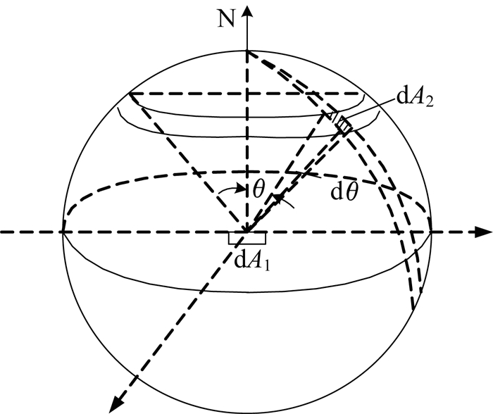
Natural light can be seen as a cosine radiator, its characteristics is the luminance in any direction measured at arbitrary points roughly the same, which means the observation point is comparable to be placed at the center of tremendous glowing sphere with uniform luminance, as shown in figure 1.
|
Figure 1 Schematic diagram of observation point |
We can observe a certain spatial angle range with the LLL gunsught, this certain spatial range is represented by the field of view.The light in the field of view can enter the low-light sight and be image on the photocathode cathode surface of the image intensifier, and the glimmer outside the field of view can not reach[8].
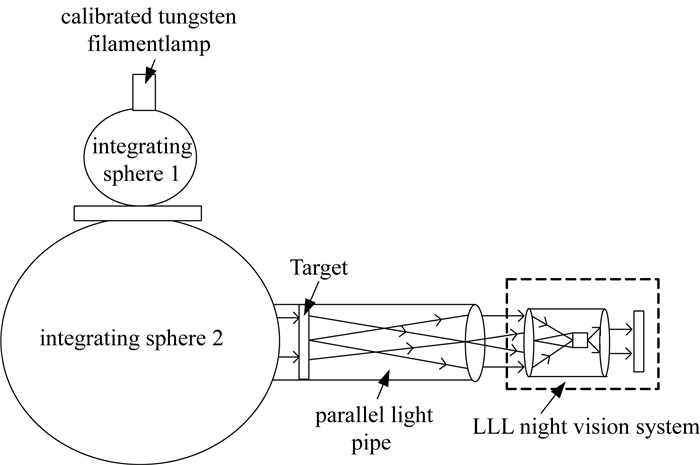
2 Simulation of natural LLL stress sourceAccording to 1.2, the effect of LLL gunsight is only from the natural light within the field angle and the field angle of LLL gunsight is generally small, therefore natural light can be simulated by using large-aperture parallel light pipe with uniform luminance in the laboratory and the simulated light has equivalent effect to natural light.LLL test system structure diagram is shown in the figure 2.
|
Figure 2 LLL test system structure system structure diagram |
When measuring the illumination in some direction, with an illuminometer, the illumination generated from the light source in the range of about 2π solid angle on its front is measured.According to the characteristics of natural light, the light source is a sphere whose radius is R(Rmax) and its brightness is L with the measuring point as the center[9].
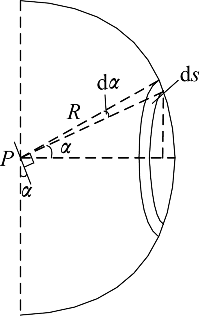
As shown in figure 3, the area of surface P of illuminometer is A, and the integral surface is the hemisphere of R(R is much larger than the diameter of P) from the center of the object mirror, thus the annular differential element between angle and angle from P can be regarded as a rectangle that the length is the circumference of the circle with angle from surface P and the width is the chord length of corresponding angle, the differential elements area is:

|
(1) |
|
Figure 3 Schematic diagram of light energy radiation |
Thus, the luminous flux generated on the illuminometer surface by the area source of such differential element:

|
(2) |
The irradiation angle of natural light for illuminated surface is 2π solid angle on its front, i.e.the integral angle α is from 0 to π/2, therefore the luminous flux generated on the illuminated surface by the sphere with luminance of L is:

|
(3) |
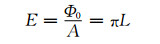
The illuminance of corresponding natural light is:
|
(4) |
Similar to the measurement of light intensity with illuminometer, the luminous flux received on the illuminated surface by LLL microscopy in the natural environment is:

|
(5) |
In formula(5), 2β is the field angle of LLL microscopy, thus the illuminance generated on illuminated surface of LLL microscopy by natural glimmer is:
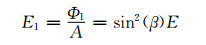
|
(6) |
By equation(4), we can get:
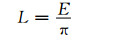
|
(7) |
When simulating natural light with a collimator, if the field angle of parallel light pipe is 2θ, the illumination generated on the illuminated surface of LLL gunsight's objective lens:

|
(8) |
Lp—Luminance at the exit of collimator;
Ep—Illuminance at exit of collimator.
Light through the frosted glass, small integral ball, the ball is integral to diffuse reflection and radiation by cosine distribution, the light exit of M is approximately qual to the brightness of the E illumination.The light intensity does not change with the direction, and has the following relations with the light emission degree and the light intensity:

|
(9) |
There will be light loss when the light passes through the collimator in the integrating sphere.The main reason for the loss of light energy is the reflection and absorption of the optical energy loss.When the light tube is designed, it can enhance the projection ability of the light by coating the film on the dividing and the light tube lens, so the absorption and reflection of the light in the light tube can be rarely seen.Under the condition of no absorption, we can get the relation between the light intensity at the exit of the large integral sphere and the light intensity at the exit pupil of the light tube:

|
(10) |
By formula (8), (9) and (10) we can get:

|
(11) |
Ls—Luminance at the exit of the large integral sphere;
Es—Illuminance at the exit of the large integral sphere.
According to this relationship, we can simulate the natural light with the illuminance of E with the help of the parallel light pipe with view angle of 2θ(2θ is greater than 2β) and illumination of EA=E1 at exit pupil.
3 Characteristics of simulated LLL stress source 3.1 Simulated glimmer has single parameterFrom formula (11), in the simulated specific natural glimmer illumination, the illuminance EA at exit pupil of parallel light pipe is solely determined by the field angle of the parallel light pipe itself and the illuminance at the exit of large integrating sphere has nothing to do with the differences of test objects.Therefore, for the simulation of different illuminance of natural light, without changing the parallel light pipe's field angle, the illumination E of parallel light pipe is the only parameter that needs changing.
3.2 Determination of simulated LLL parametersBy comparing Formula (6) and Formula (8), it shows that when θ > β, the effective illumination of simulated LLL entering LLL microscope:
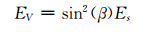
|
(12) |
when θ > β, the effective illumination of simulated glimmer entering LLL microscope:

|
(13) |
Therefore, in actual measurement the field angle of the parallel light pipe must be larger than that of the measured LLL microscope.Through the statistics and analysis of the magnitude of existing field angle, it is determined that 2θ must be greater than 10 degrees.
3.3 Simulated glimmer is applicable to all kinds of LLL microscopeDifferent types of LLL microscopes have different characteristics, such as the fixed focus or zoom lens, etc..So it requires the distance from the target provided to be larger than the minimum observation distance of LLL microscope, so for different light microscopes, the glimmer simulated by all parallel light pipes is applicable.Because the device of simulated glimmer is parallel light pipe, set a reticle as the target to provide for LLL microscopy in its focal plane, which is equal to the target at infinity, meeting the requirement that the distance between the target and LLL microscope must be greater than the minimum distance of observation.
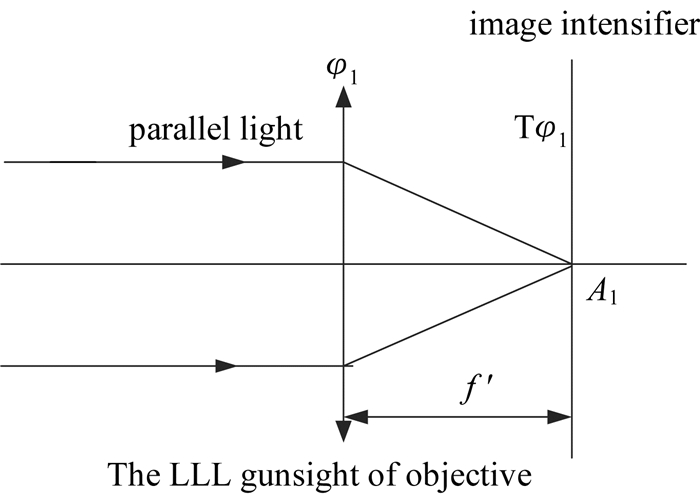
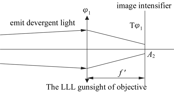
3.4 Optical stress of simulated glimmer is slightly greater than that of natural lightIn theory, when the optical stress of glimmer simulated by the parallel light pipe and that of natural LLL project on the LLL gunsight, if the light illumations of them are same, their effects are same on sighting telescopes[10].Generally, projection on objective lens of LLL gunsight, the former emit parallel light, as shown in figure 4; and the latter emit divergent light, as shown in figure 5, the light illuminates through objective lens on the receiving surface(image intensifier), they have different effects on light receiving surface, therefore there's some deviation in the simulation of natural glimmer using parallel light pipes.
|
Figure 4 Schematic diagram of parallel light pipe effect |
|
Figure 5 Schematic diagram of natural LLL effect |
After the light going through LLL gunsight lens, there will be optical energy loss, which has mainly two factors:① reflection loss of projection plane; ② absorption loss of projective material.
(1) The reflection loss of the projection plane:set the number of K for the refractive surface, R for the reflectivity, T for the transmittance.According to the actual situation, if taking K=14, R=1%,

|
(14) |
T1—the sum of transmittance remove from reflection loss.
(2) Absorption loss of projection material:set αas absorptivity, ∑d as the sum of the center thickness of the projection materials.Take α=0.015, ∑d=3 cm, so:

|
(15) |
T2—the sum of transmittance remove from absorption loss.
Therefore, the total transmission rate is:

|
(16) |
By formula (5) and (12), the luminous flux received by objective lens of LLL microscope is Φ1=sin2(β)πLA, therefore, the luminous flux arriving at image intensifier is:
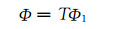
|
(17) |
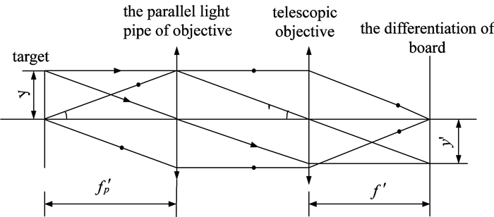
As shown in figure 3 and 4, the luminous flux arriving at image intensifier is Φ, the effects of parallel light and divergent light are different, because the surface areas of projected light spots on image intensifier A1, A2are different.According to formula E=Φ/A, the illuminance E is inversely proportional to the surface area A of projection light spot.
As shown in figure 6, the projection light spot size formed by the parallel light action is:

|
(18) |
|
Figure 6 Optical pathway diagram of parallel light pipe effect |
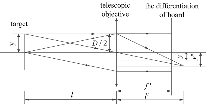
As shown in figure 7, the natural light effect on the formation of the projected spot size:
|
Figure 7 Schematic diagram of natural LLL effect |
By Gauss formula:
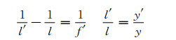
|
(19) |
And similar triangles:
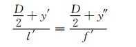
|
(20) |
We can get:

|
(21) |
By comparison of formula (18), (19), regard the image as a square with side length of y′, y″, we can get A1 < A2.
Thus, with a parallel beam simulation of natural light, the image intensifier light stress is higher than that of natural light, when l is large, l′=f′ at this time A′1=A′2, so the quite small difference can be neglected.
3.5 Experimental test and data processingAt night the sky can be divided into months and months of the situation, below we will have several typical weather conditions for laboratory simulation experiments[11].Table 1 lists the approximate values of the illumination of the ground surface under several typical weather conditions.In order to make the laboratory simulation of night light days and the nature of the real value is closer, we conducted a number of field measurements at the same spot under different weather conditions at night sky illumination, and the use of LLL gunsight were observed.Table 2 lists the real values of the illumination of the ground surface under several typical weather conditions.
|
Table 1 Approximate values of ground background illumination in the several typical weather conditions |
|
|
Table 2 Real value of ground background illumination in the several typical weather conditions |
Because of the existence of the village, which is not far from the measurement site, the measured value is slightly higher than the theoretical value.
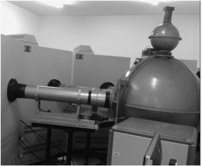
As shown in figure 8, the experimental system consists of light source, integrating sphere, parallel light tube, weak light meter and stabilized power supply etc.
|
Figure 8 The physical composition of the LLL stress source test system |
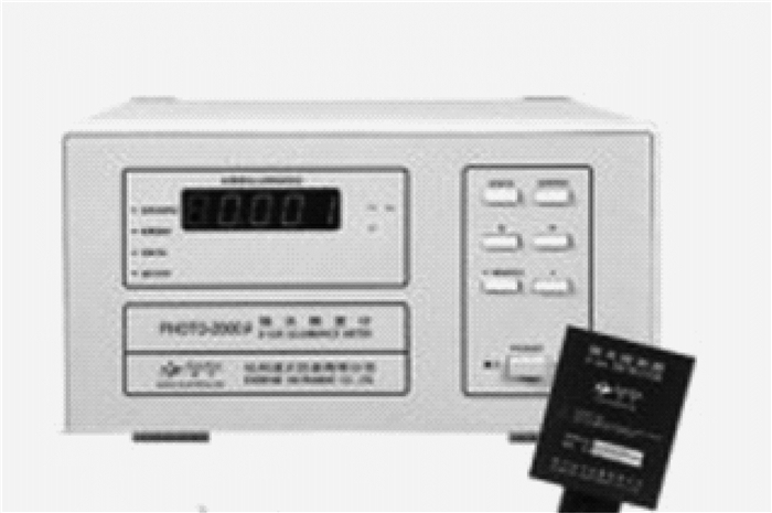
Illuminance meter using Hangzhou distance PHOTO-2000U;Measurement range is 1×10⁻⁶~9 lx; Measurement accuracy is 1×10⁻⁶ lx, figure 9 is the physical drawing of illuminometer:
|
Figure 9 Physical diagram of the LLL illuminometer |
Light source is composed of bromine tungsten lamp(12 V, 75 W), integrating sphere and stabilized power supply.Bromine tungsten lamp color temperature is 3 200 K; Two integral ball has a uniform light illumination and weaken the effect on light, equipped with adjustable diaphragm at the connection between the light source and the integrating sphere.In order to eliminate or reduce the load resistance and the temperature changes of the output current, the light source adopts constant current power supply[12].Parallel light tube uses the objective lens focal length 600 mm, the field of view angle 10 degrees, the diameter 120 mm big diameter parallel light tube.
During the measurement, the illuminometer is placed at the exit of the large integrating sphere, by adjusting the constant current power supply to control the luminance of bromine tungsten lamp so that the illumination at the exit of the large integrating sphere Es is equal to the corresponding theoretical values in table 1.At the exit of parallel light tube, 5 points were randomly selected to measure and record the illumination value[13].Then, the illumination meter was placed in the parallel light tube exit pupil to observe the pupil's illumination.If the measured illumination value at the exit of parallel light pipe is EA corresponding to the theoretical value derived by formula (11), it is indicated that the simulation of natural glimmer is reasonable.Table 3 to table 5 are the illumination values measured under several typical weather conditions.
|
|
Table 3 Illumination value under simulated full-moon and sunny condition |
|
|
Table 4 Illumination values under simulated full-moon condition with light clouds |
|
|
Table 5 Illumination values under simulated half-moon and sunny condition |
Table 3 to table 5 shows that the experimental measurement data is consistent with the theoretical value of the formula, the experimental system can realize the accurate simulation of the typical night sky.
4 ConclusionsCompared to traditional simulation environment tests, the parallel light pipe is used to simulate natural light, in which the method is simple, parameters can be easily determined, the equipment fabrication is not complicated, the simulation has high precision, and it saves the expenditure compared with the darkroom simulation, because most night vision sighting telescopes belong to the telescope system and their imaging distance is relatively longer, which is more suitable for large darkroom or the field.However, for the construction of a darkroom with a length up to a few hundred meters and equipped with other facilities, the expenditure is very high, and the external conditions for field measurements are very difficult to control.At this stage, there is little information that comprehensively reflects the LLL stress source simulation.Therefore, for the detection of LLL night vision system should study the source simulation, still have important meaning for us.
| [1] | WANG J H, JIN W Q, WANG X. General performance evaluation for direct viewing low light level imaging systems based on minimum resolvable contrast[J]. Acta Armamentarii, 2010, 31(2): 184–190. |
| [2] | GUO H, XIANG S M, TIAN M Q. A review of the development of low-light night vision technology[J]. Infrared Technology, 2013, 35(2): 63–68. |
| [3] | JIN W Q, GAO Z Y, SU X G, et al. On the problem of matching between optoelectronics imaging system and human vision[J]. Infrared Technology, 2000, 22(5): 40–44. |
| [4] | LIU L, LI Y, QIAN Y S, et al. New method for visual range evaluation and scene simulation of low-light-level(LLL) night vision systems[J]. Journal of Applied Optics, 2006, 27(6): 546–551. |
| [5] | YANG L. Study on the low-light level stress source system of low-light level night vision device testing equipment[D]. Changchun: Changchun University of Science and Technology, 2014. YANG L. Study on the low-light level stress source system of low-light level night vision device testing equipment[D]. Changchun: Changchun University of Science and Technology, 2014. |
| [6] | YE Y L, WU X R. Simulation of low-light-level condition in laboratory[J]. Laser & Infrared, 2005, 35(12): 942–943. |
| [7] | SHI J F, LIU Y. Night sky radiation simulation for test of low-level-light night vistion systems[J]. Journal of Applied Optics, 2003, 24(5): 11–13. |
| [8] | SU M K, GAO Z Y, KANG J J. The infection of surroundings illuminate on low-light-level night-vision device[J]. Laser & Infrared, 2003, 33(4): 313–315. |
| [9] | DRIGGERS R G, JACOBS E L, VOLLMERHAUSEN R H. Current infrared target acquisition approach for military sensor design and wargaming[J]. Proceedings of SPIE, 2006, 6207: 620709. DOI:10.1117/12.660963 |
| [10] | BAI L F, QIAN W X, ZHANG Y, et al. Analysis and study on the stadia of low light level imaging system[C]//Proceedings Volume 5633, Advanced Materials and Devices for Sensing and ImagingⅡ. Beijing, China: SPIE, 2015. BAI L F, QIAN W X, ZHANG Y, et al. Analysis and study on the stadia of low light level imaging system[C]//Proceedings Volume 5633, Advanced Materials and Devices for Sensing and ImagingⅡ. Beijing, China: SPIE, 2015. |
| [11] | GABER L. Optical sight system with wide range of shooting distances: US, US6487809B1[P]. 2002-12-03. GABER L. Optical sight system with wide range of shooting distances: US, US6487809B1[P]. 2002-12-03. |
| [12] | SU C Z, CAO G H, XU H J. Relationship analysis of output illuminance of integrating sphere and incident beam geometry[J]. Laser & Infrared, 2010, 40(2): 195–199. |
| [13] | YU Q S, AN Z Y, YANG R N, et al. Test of Parallax parameters for optoelectronic sights in small arms[J]. Optics and Precision Engineering, 2010, 18(8): 1732–1737. |